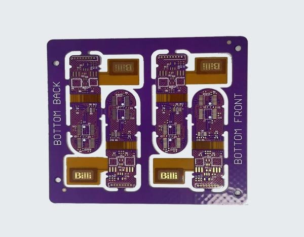
Rigid Flex pcb design guidelines

Andwin provide Flex PCB and Rigid-flex PCB for customer, email us now for you PCB quote, Email is : contact@andwinfpc.com
Material considerations for Rigid-Flex PCB Design
Talk to your manufacturer to ensure you select the right material for your rigid-flex design
You’ll want to consult your PCB manufacturer before starting a design. Depending on whether the PCB is meant for dynamic bend or stable bend, the choice of copper type, the number of layers, bend radius, and coverlays may differ.
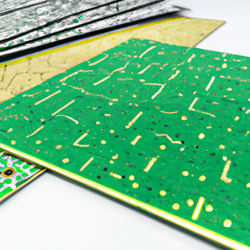
A dynamic bend rigid-flex PCB is installed in an environment where it will constantly be subjected to bending. Therefore, it is recommended to use no more than 2 layers and ensure that the bending radius is at least 100 times the material thickness.
Meanwhile, it’s possible to have up to 10 to 20 layers for a rigid-flex PCB that’s meant for stable-bend installations. It is not subjected to repeated bending force and that means a smaller bending radius of about 10 times its material thickness is also possible.

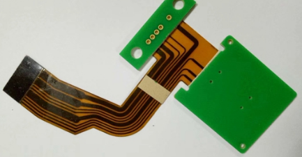
Rigid Flex pcb design guidelines
Material Selection: Choose the right materials for your design. The most common materials used for rigid-flex PCBs are FR-4 and polyimide. Make sure to select the right materials based on your design requirements.
Bend Radius: The bend radius is the minimum radius that a flex circuit can bend without causing damage. The bend radius should be carefully considered during the design phase to avoid any damage to the circuit.
Trace Width and Spacing: The trace width and spacing should be carefully considered to ensure that the circuit can handle the required current and voltage. The spacing should be increased in areas where the circuit will be bent.
Via Placement: The via placement should be carefully considered to ensure that the circuit can handle the required current and voltage. Vias should be placed away from areas where the circuit will be bent.
Manufacturing: Manufacturing should be carefully considered to ensure that the circuit is manufactured to the required specifications. The manufacturing process should be carefully monitored to ensure that there is no damage to the circuit during the manufacturing process.
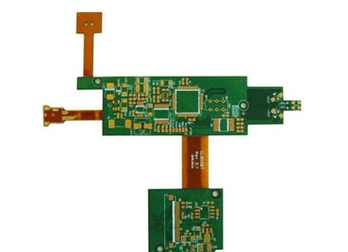
Component Placement: Component placement should be carefully considered to ensure that the components are placed in areas where the circuit will not be bent. Components should be placed in areas where they will not interfere with the bending of the circuit.
Stiffeners: Stiffeners are used to provide additional support to the circuit in areas where it will be bent. Stiffeners should be carefully designed and placed to ensure that they provide the required support.
Testing: Testing should be performed on the circuit to ensure that it meets the required specifications. Testing should be performed on the circuit before and after bending to ensure that there is no damage to the circuit.
About Andwin FPC
Since our founding in 2006, Andwin FPC has been leading Flex & Rigid-flex PCB technology across several markets,
we are proud to serve a wide range of industries, including aerospace, medical,automotive, and telecommunications.
Our flexible PCB and Rigid-flex PCBs are used in a variety of applications,from simple electronic devices to complex systems that require high reliability and performance.
At Andwin, we are dedicated to providing our customers with the highest quality PCBs, exceptional service, and competitive pricing.
We are committed to continuous improvement and innovation, and we are always looking for ways to better serve our customers and stay ahead of the competition.
The following is a list of the services and products.