
How to Design Rigid-Flex PCBs: Key Guidelines and Tips
Designing rigid-flex PCBs can be a complex yet rewarding endeavor, as these boards offer the advantages of both rigid and flexible circuit technologies.
With their unique design and construction, these boards can handle intricate layouts and a variety of application demands.
Understanding how to design rigid-flex PCBs is essential for engineers aiming to create reliable and efficient electronic components. Below, we’ll explore the key guidelines and tips to ensure successful design.
Understanding Rigid-Flex PCBs
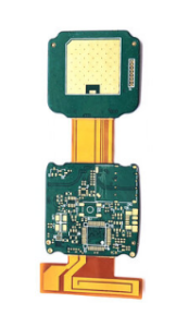
Rigid-flex PCBs combine rigid and flexible substrates into a single board, allowing for a configuration that can fit in tight spaces while maintaining structural integrity.
This hybrid design enables designers to create compact and lightweight products, ideal for industries such as aerospace, healthcare, and consumer electronics.
Understanding their arrangement is crucial, as it affects everything from circuitry to manufacturing processes.
Key Components of Rigid-Flex Designs
- Material Selection: The choice of materials is fundamental in designing rigid-flex PCBs.
Common materials include polyimide for flexibility and FR-4 for the rigid sections.
Selecting the right substrate influences the board’s thermal, mechanical, and electrical properties. - Layer Stack-up: A well-structured layer stack-up is vital. Rigid-flex boards typically consist of multiple layers of both rigid and flexible materials.
Consider the overall thickness and how the layers will integrate with components and assemblies, as this affects both performance and manufacturability. - Via Types: Different via types function in rigid-flex PCBs, including blind, buried, and through-hole vias.
Designing the right type of vias for the respective layers helps maintain signal integrity while minimizing the complexity of the board layout.
Design Considerations for Rigid-Flex PCBs
When embarking on the design process, several considerations can significantly impact the board’s performance and reliability.
1. Mechanical Stress Factors
Rigid-flex PCBs will often experience bending and flexing in their applications.
As such, it is essential to evaluate mechanical stress points during the design phase.
Pay particular attention to areas where the rigid meets the flex, as these joints are most vulnerable.
2. Component Placement
Effective component placement is crucial.
Prioritize placing heavier components on the rigid sections of the board to distribute weight appropriately.
Furthermore, ensuring that components do not impede the bending areas will improve overall durability and performance.
3. Bend Radius Specification
The minimum bend radius must be defined based on the application requirements.
Generally, a bend radius of 5–10 times the thickness of the flexible area is recommended.
This specification will help in preventing damage to the PCB during installation and use.
Simulation and Testing
Before finalizing your design, leveraging simulation tools can be immensely beneficial.
Software that facilitates finite element analysis (FEA) allows you to visualize how the PCB will react to physical stresses and thermal changes.
Conducting Prototype Tests
Once the design is simulated, creating prototypes for testing is a vital step.
These prototypes allow you to assess performance in real-world applications and identify potential weaknesses.
Testing for various parameters, including electrical performance and mechanical integrity, will provide you with invaluable data to refine your design.
Manufacturing Process
The manufacturing phase of rigid-flex PCBs can differ from standard boards due to the intricate nature of the designs.
Here are a few important considerations:
1. Fabrication Techniques
Rigid-flex board manufacturing may involve both subtractive and additive techniques.
Make sure to communicate clearly with your fabrication partner about the specifics of the design to ensure compatibility.
2. Quality Control
Finally, never overlook quality control.
Rigid-flex PCBs are complex, and rigorous testing protocols should be in place to catch any defects or inconsistencies early on.
Implementing automated optical inspection (AOI) and electrical testing can provide assurance in the PCB’s performance.
Conclusion
Understanding how to design rigid-flex PCBs is a multifaceted process that requires attention to detail and a grasp of various mechanical and electrical principles.
By selecting the right materials, being mindful of mechanical stress, employing proper design practices, and conducting thorough testing, you can create robust and reliable rigid-flex PCBs that meet the demands of modern electronic applications. With these guidelines and tips in mind, you are well on your way to mastering the art of rigid-flex PCB design.