
How to Design Rigid-Flex PCBs: Key Guidelines and Tips
Designing rigid-flex PCBs involves a unique set of challenges and opportunities compared to traditional printed circuit boards (PCBs).
Rigid-flex PCBs combine the benefits of both rigid and flexible substrates, making them ideal for applications where space is at a premium and mechanical reliability is paramount.
To assist designers in crafting effective rigid-flex PCBs, this article outlines key guidelines and tips that ensure a successful design.
Understanding Rigid-Flex PCB Structure
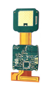
Before diving into the design process, it’s crucial to understand the structure of rigid-flex PCBs.
These boards consist of a combination of rigid and flexible materials, typically polyimide for the flexible part and FR-4 for the rigid sections.
The flexible areas allow for bending and folding, which is particularly useful in compact devices like smartphones, wearables, and medical devices.
Material Selection
When designing rigid-flex PCBs, material selection is critical. The behaviors of the flexible and rigid parts under thermal and mechanical stresses must be considered.
Look for high-quality flexible materials like polyimide, which offer superior thermal stability and excellent dielectric properties.
Additionally, ensure that the materials you choose are compatible with the soldering processes you intend to use.
Key Guidelines for Rigid-Flex PCB Design
1. Follow Design Rules
Rigid-flex designs have specific manufacturing constraints that must be adhered to.
Ensure that your design follows the manufacturer’s design rules, which often include guidelines on minimum trace width and spacing, hole diameter, and layer count.
Larger trace widths are typically preferred in flexible sections to enhance durability.
2. Plan Layer Stackup
A robust layer stackup is crucial for the integrity of the board. Typically, a rigid-flex PCB will consist of multiple layers of flexible and rigid substrates.
Design your stackup to minimize stress on the flexible layers. For instance, keep the flexible layers as thin as possible while ensuring they can handle the necessary current load.
3. Flex Areas Design
Designing the flex areas is one of the most critical parts of rigid-flex PCB design. These areas must be clearly defined within the PCB layout.
Ensure that you include appropriate flex features, such as cut-outs or notches, to facilitate bending without damaging the board.
Consider using an S-shaped design for traces in these areas to allow for movement without stress fractures.
4. Emphasize Routing
Routing is another important aspect of design. In rigid-flex layouts, it’s vital to utilize both the rigid and flexible portions effectively.
Avoid long traces in the flex sections, as they are more prone to damage when bent. Instead, use the rigid sections for these longer traces where additional stability can be provided.
Tips for Practical Implementation
Simulation Tools
Utilizing simulation tools can significantly streamline your design process. Employ Electronic Design Automation (EDA) tools tailored for rigid-flex designs to visualize stress points and ensure your PCB layout adheres to your design rules. Simulation can help predict potential issues before manufacturing, saving time and resources.
Prototyping and Testing
Once your design is complete, consider producing prototypes for testing. This step is essential in identifying any unforeseen issues with flex areas and overall mechanical performance.
A slight modification in the angle of bend or route placement can make a considerable difference in performance.
Communicate with Manufacturers
Effective communication with your manufacturer is key. Provide them with thorough documentation, including design files, specifications, and assembly instructions.
Discuss any peculiarities of your design with them, particularly those related to the flex areas, to ensure seamless production.
Conclusion
Designing rigid-flex PCBs is both an art and a science, requiring a fine balance between innovation and adherence to established guidelines.
By following the tips and guidelines outlined in this article, you can develop effective rigid-flex PCB layouts that meet your application’s functional requirements.
Remember to continually learn and adapt as technology and materials evolve—it’s vital in keeping your designs at the forefront of innovation.
Whether for automotive, consumer electronics, or medical applications, well-designed rigid-flex PCBs can elevate your products and establish a competitive advantage in the market.