
Best Practices for Rigid-Flex PCB Design: A Comprehensive Guide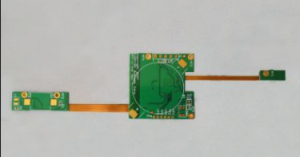
Rigid-flex PCB design is an innovative solution for a variety of modern electronics applications, offering both flexibility and robustness.
As technology continues to advance, the demand for efficient, space-saving, and reliable electronic components has grown.
This guide will cover essential best practices for designing rigid-flex PCBs, ensuring optimal performance and reliability in your final product.
Understanding Rigid-Flex PCBs
Rigid-flex PCBs combine the best features of rigid and flexible printed circuit boards.
They consist of a combination of rigid substrate areas along with flexible sections, allowing them to bend and fit into tight spaces while maintaining structural integrity.
This design approach is especially beneficial in industries such as medical devices, consumer electronics, and aerospace, where space is often at a premium.
Advantages of Rigid-Flex Designs
Before delving into the design practices, it’s crucial to recognize the benefits of rigid-flex PCBs:
- Space Efficiency: Rigid-flex designs minimize the need for connectors and wiring, leading to a more compact final product.
- Improved Reliability: Fewer components reduce the risk of failure, as connectors are often points of vulnerability.
- Weight Reduction: The integration of rigid and flexible elements can lead to significant weight savings, an essential factor in many industries.
Essential Practices in Rigid-Flex PCB Design
1. Comprehensive Planning
Effective design begins with thorough planning. Clear specifications and requirements should be established upfront, including:
- Electrical Requirements: Understand the voltage, current, and environmental conditions the PCB will face.
- Mechanical Constraints: Identify size constraints, mounting options, and stress factors likely to affect the PCB during service.
- Thermal Considerations: Evaluate heat dissipation needs, as flexible materials can suffer under high thermal stress.
2. Material Selection
The choice of materials plays a vital role in the overall performance and longevity of rigid-flex PCBs. Factors to consider include:
- Dielectric Materials: Use materials that offer good electrical properties and withstand bending without degrading.
- Copper Thickness: A thicker copper layer may be necessary to handle higher currents, while a thinner copper may suffice for lower-power applications.
- Adhesives: Choose adhesives that can maintain integrity throughout the product’s life cycle, especially where flexing occurs.
3. Design Considerations
When creating the layout for your PCB, several factors should be kept in mind:
- Layer Stack-Up: Carefully plan the stacking of rigid and flexible layers to ensure optimal signal integrity and minimize potential issues related to bending.
- Trace Widths and Spacing: Follow established design rules for trace widths and spacing to minimize electromagnetic interference (EMI) and crosstalk in your design.
- Via Types: Use appropriate via types for flexible parts of the PCB, often employing blind or buried vias, to maintain the flexibility and minimize stress during bending.
4. Bending and Folding Areas
One of the unique aspects of rigid-flex PCBs is their ability to bend. Properly designing these areas is essential:
- Bend Radius: Determine the appropriate bend radius to prevent failure during flexing. Different materials will have different bend capabilities.
- Flex Design Guidelines: Follow industry-standard guidelines for designing flex areas, ensuring uniform bends and a gradual transition between rigid and flexible sections.
5. Design for Manufacturability (DFM)
Engaging in DFM practices early can streamline production and reduce costs. Keeping the following points in mind will facilitate a smoother manufacturing process:
- Avoid Sharp Corners: Design rounded corners to enhance durability and prevent tearing.
- Sufficient Clearance: Ensure that components have adequate clearance from edges and bends.
- Fabrication Constraints: Be aware of limitations in both rigid and flexible manufacturing processes and incorporate them into your design.
6. Testing and Validation
Once your design is complete, rigorous testing and validation are essential to ensure performance reliability:
- Electrical Testing: Conduct tests to ensure that the PCB meets all electrical specifications.
- Mechanical Testing: Perform physical tests, including flex and bend tests, to validate the design under real-world conditions.
Conclusion
Designing rigid-flex PCBs is a complex task that combines careful planning, material selection, and adherence to best practices.
By focusing on these strategies—from initial specifications to testing and validation—you can create reliable, high-performance circuit boards that meet the needs of modern electronics.
Staying informed about the latest trends and technologies will further enhance your design capabilities, allowing you to harness the full potential of rigid-flex technology in your projects.