
Manufacturing Considerations in Rigid-Flex PCB Design: A Step-by-Step Guide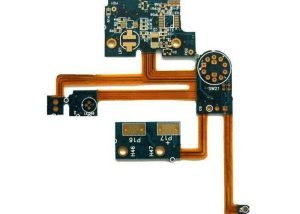
Manufacturing considerations in rigid-flex PCB design are crucial for anyone involved in the electronics industry.
As devices become more compact and integrated, the need for rigid-flex circuit boards—combining rigid and flexible substrates—grows.
This guide will walk you through the essential considerations while designing these boards to ensure manufacturability, reliability, and performance.
Understanding Rigid-Flex PCBs
Rigid-flex PCBs are a hybrid solution combining the benefits of both rigid and flexible circuit boards.
They enable designers to create complex shapes and layouts while providing the durability associated with rigid boards.
When embarking on the design process, it is vital to understand how these different materials work together and the implications they have on performance and manufacturability.
Step 1: Define Your Application Requirements
Before diving into the design, it’s important to have a clear understanding of your application requirements.
Consider the following questions:
- What is the intended function of the PCB?
- What are the dimensional constraints?
- Will the board need to withstand extreme temperatures or humidity?
- Is there a need for specific mechanical or electrical properties?
Documenting your requirements will guide material selection, layer stack-up, and manufacturing choices.
Step 2: Material Selection
The choice of materials is one of the most significant factors influencing the manufacturability of rigid-flex PCBs.
Typically, these boards use FR4 for the rigid sections and polyimide for the flexible parts. Some considerations during this selection process include:
- Thermal Properties: Ensure materials can handle the thermal profiles during manufacturing and operation.
- Dielectric Properties: Low dielectric constant materials can benefit high-frequency applications, while those with appropriate dielectric strength can prevent signal crosstalk.
- Mechanical Strength: Assess mechanical flexibility vs. rigidity needed for your application.
Consult with suppliers to ensure that the materials meet the regulatory standards and implementation guidelines required for your applications.
Step 3: Layer Stack-Up
Creating an appropriate layer stack-up is essential for ensuring electrical performance and mechanical integrity.
In rigid-flex designs, you typically have alternating layers of rigid and flexible materials. Key considerations during this phase include:
- Number of Layers: Understand the number of layers required based on your design complexity and space constraints.
- Impedance Control: Maintaining controlled impedance is critical for high-speed signal integrity. Plan the dielectric thickness and dimensions accordingly.
- Flex Regions: Pay attention to how you configure your flex regions, ensuring they are located in areas that will not subject them to excess stress during bending.
Step 4: Design Considerations
Once you have your material and stack-up determined, it’s time to focus on the design aspects.
When crafting your PCB layout, keep the following in mind:
- Trace Width and Spacing: Proper trace width and spacing are crucial for avoiding signal integrity issues.
Use design rules that align with the manufacturing capabilities of your selected PCB fabricator. - Radiuses in Flexible Sections: Ensure that bends in the flexible areas have appropriate radii to avoid stress fractures.
A minimum bend radius generally equals 5x the thickness of the material. - Via Types: Use blind or buried vias when possible to save space and avoid signal loss in flexible areas, ensuring they are tested for reliability based on flexing cycles.
Step 5: Prototyping and Testing
Before full-scale production, prototyping is necessary to validate your design.
Consider the following:
- Initial Tests: Conduct electrical testing on prototypes to ensure that all connections are functioning as expected.
- Mechanical Testing: Assess how the PCB performs under real-world conditions, including bending, thermal cycling, and environmental stress tests.
Utilizing thermographic cameras and other testing equipment can help in identifying weaknesses in the design during prototyping.
Conclusion: Collaboration with Manufacturers
Choosing the right manufacturer is crucial in ensuring that your designs transition smoothly from concept to production.
Communication is key—discuss your design constraints and expectations early in the process, and be open to their recommendations.
By focusing on manufacturing considerations in rigid-flex PCB design from the onset, you greatly enhance your chances of meeting project goals on time and within budget.
Engaging with knowledgeable manufacturers can make the difference between a successful prototype and costly errors down the road.
By following these steps, you can ensure that your rigid-flex PCB designs are not only innovative but also manufacturable and reliable in the long run.