
Introduction
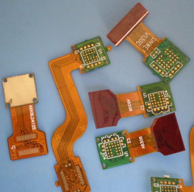
Rigid-flex printed circuit boards (PCBs) are a hybrid solution combining the durability of rigid boards with the adaptability of flexible circuits.
They are widely used in industries where reliability under extreme conditions—such as high vibration, shock, or thermal stress—is critical.
Applications range from aerospace and military systems to medical implants and consumer wearables.
This guide explores key rigid-flex PCB design considerations, including material selection, bend radius, layer stackup, and thermal management.
Following these guidelines ensures optimal performance, longevity, and manufacturability.
Pain Points Solved by Rigid Flex PCBs
1. Harsh Environmental Conditions
Rigid-flex PCBs excel in environments with:
- High shock and vibration (e.g., aerospace, automotive, industrial machinery).
- Extreme temperatures (e.g., military-grade electronics, satellite systems).
- Chemical exposure (e.g., medical sterilization, industrial sensors).
2. Space and Weight Constraints
- Miniaturization: Ideal for compact devices like pacemakers, hearing aids, and drones.
- Weight reduction: Critical in aerospace and wearable technology.
3. Enhanced Reliability
- Fewer interconnects: Eliminates connectors, reducing failure points.
- Dynamic flex endurance: Can withstand thousands of bend cycles without damage.
When to Use Rigid Flex PCBs
Rigid-flex PCBs are ideal when:
- Multiple rigid boards need interconnection without bulky connectors.
- Space is limited, requiring 3D circuit routing.
- Weight reduction is crucial (e.g., drones, satellites).
- High mechanical stress (bending, twisting, vibration) is expected.
While rigid-flex PCBs may have higher initial costs than traditional rigid boards, they reduce assembly complexity, improve reliability, and lower long-term maintenance costs.
Rigid Flex PCB Design Guidelines
1. Flex-to-Rigid Transitions
The transition between rigid and flexible sections is a critical stress point. Key considerations:
- Smooth transitions prevent cracking or delamination.
- Keep-out zones: No traces, vias, or pads should be placed within a specified margin (typically 0.050” or 1.27mm) from the transition.
- Reinforcement: Stiffeners (e.g., polyimide or FR4) may be added near bends to reduce stress.
2. Bend Radius Considerations
The minimum bend radius must be carefully calculated to prevent conductor damage:
- For 1-2 layer flex circuits: 6x the total flex thickness.
- For 3+ layer flex circuits: 12x the total flex thickness.
- Static vs. dynamic bends:
- Static bends (permanent folds) can tolerate tighter radii.
- Dynamic bends (repeated flexing) require larger radii for longevity.
3. Material Selection
Flexible Materials
- Polyimide (PI): Most common (high thermal resistance, flexibility).
- PEN/PET: Lower-cost alternatives for less demanding applications.
Rigid Materials
- FR4: Standard for rigid sections.
- High-Tg FR4: For high-temperature environments.
Adhesives & Prepregs
- No-flow prepregs prevent resin from seeping into flex areas during lamination.
- Adhesiveless laminates improve flexibility and reduce thickness.
4. Layer Stackup and Count
- Symmetrical stackups prevent warping (e.g., copper balancing).
- Flex layers should run continuously through rigid sections for reliability.
- Typical configurations:
- 1-4 flex layers (common in wearables, medical devices).
- Up to 20+ layers (high-density aerospace/military applications).
5. Trace Routing and Via Placement
Trace Design
- Wider traces in flex areas (reduces stress concentration).
- Avoid sharp angles (use curved or 45° traces).
- Neckdowns (tapered traces) should occur after the flex-to-rigid transition.
Via Placement
- Avoid vias in bend areas (risk of cracking).
- Minimum 0.050” (1.27mm) from flex-to-rigid transitions.
- Plated through-holes (PTHs) should be reinforced in rigid sections.
6. Thermal Management
- High-power components should be placed on rigid sections (better heat dissipation).
- Thermal vias help transfer heat away from critical components.
- Flex areas dissipate heat naturally due to thin materials but should avoid high-power traces.
Conclusion
Designing rigid-flex PCBs requires careful planning to balance flexibility, durability, and electrical performance. Key takeaways:
✅ Minimize stress at flex-to-rigid transitions.
✅ Follow bend radius rules to prevent conductor damage.
✅ Use appropriate materials (polyimide for flex, FR4 for rigid).
✅ Optimize trace routing for mechanical reliability.
✅ Collaborate with manufacturers early to avoid costly redesigns.
For high-reliability applications, rigid-flex PCBs offer unmatched advantages in weight savings, space efficiency, and long-term durability.
Need a custom rigid-flex PCB solution? Contact ivy@andwinpcb.com for a design consultation or quote!