Rigid-Flex PCB Bending Radius: A Crucial Consideration in Designing Flexible Printed Circuit Boards
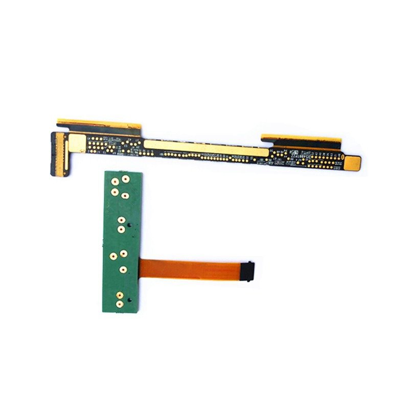
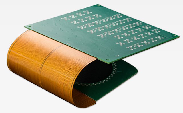
Flexible printed circuit boards (PCBs) have revolutionized the electronics industry by enabling the creation of compact, lightweight, and highly flexible electronic devices. These boards are designed to be bent, folded, or twisted to fit into tight spaces or conform to irregular shapes, making them ideal for applications such as wearable technology, medical devices, and aerospace systems. However, it is essential to understand the concept of bending radius when designing rigid-flex PCBs to ensure their reliability and longevity.
Andwin provide Flex PCB and Rigid-flex PCB for customer, email us now for you PCB quote, Email is : contact@andwinfpc.com
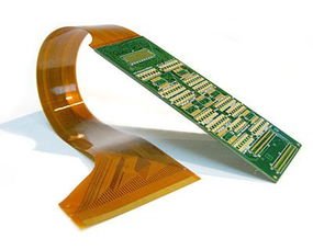
The bending radius refers to the minimum radius that a flexible PCB can be bent without causing damage to the board or its components. It is crucial to determine the appropriate bending radius during the design phase to prevent issues such as stress concentration, material fatigue, and electrical failures. A smaller bending radius can lead to excessive strain on the board, resulting in cracks, fractures, or broken traces, while a larger bending radius may compromise the flexibility and functionality of the PCB.
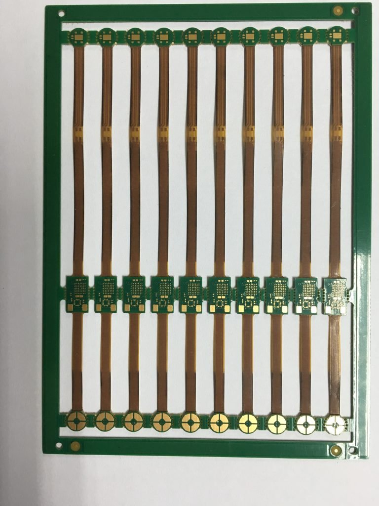
The bending radius of a rigid-flex PCB depends on various factors, including the thickness and type of materials used, the number of layers, the size and placement of components, and the intended application. Generally, the bending radius is determined by the thickest and least flexible layer in the PCB stack-up. For instance, if a rigid layer is sandwiched between two flexible layers, the bending radius will be determined by the rigid layer’s properties.
To ensure the reliability of a rigid-flex PCB, it is crucial to follow the manufacturer’s guidelines and industry standards for bending radius. These guidelines typically specify the minimum bending radius that should be maintained during installation, operation, and maintenance of the PCB. It is essential to note that exceeding the recommended bending radius can lead to mechanical stress, delamination, and premature failure of the board.
Designers must also consider the type of flexing that the PCB will undergo. There are two primary types of flexing: dynamic and static. Dynamic flexing involves repeated bending or flexing of the PCB during operation, while static flexing refers to a one-time bending or flexing during installation or maintenance. Dynamic flexing requires a larger bending radius to accommodate the repeated stress, while static flexing may allow for a smaller bending radius.
Additionally, the choice of materials plays a significant role in determining the bending radius of a rigid-flex PCB. Flexible materials such as polyimide (PI) or polyester (PET) offer better flexibility and can withstand smaller bending radii compared to rigid materials like FR4. However, the trade-off is that flexible materials may have limitations in terms of electrical performance or mechanical strength.

About Andwin FPC
Since our founding in 2006, Andwin FPC has been leading Flex & Rigid-flex PCB technology across several markets,
we are proud to serve a wide range of industries, including aerospace, medical,automotive, and telecommunications.
Our flexible PCB and Rigid-flex PCBs are used in a variety of applications,from simple electronic devices to complex systems that require high reliability and performance.
At Andwin, we are dedicated to providing our customers with the highest quality PCBs, exceptional service, and competitive pricing.
We are committed to continuous improvement and innovation, and we are always looking for ways to better serve our customers and stay ahead of the competition.
The following is a list of the services and products.